Lab 2: Forward Kinematics
Goal
Implement forward kinematics for the right front leg of the Pupper robot using ROS2 and Python.
Here’s what your implementation should look like when complete:
Fill out the lab document as you go. Make a copy and add your responses.
Part 1: Hardware Build
Follow the build instructions for lab 2
📝 Open build instructions in new tab 📝You will build a front right leg for Pupper in this lab. Begin by checking to see that your kits contain all the pieces, if not, please ask a TA.
Part 2: Setup
Make sure you have completed Lab 1 and are familiar with the ROS2 environment on your Raspberry Pi 5.
Clone the lab 2 code repository on the Raspberry Pi:
cd ~/
git clone https://github.com/cs123-stanford/lab_2_2024.git lab_2
Open the workspace (lab_2 directory) in VSCode and examine the
lab_2.pyfile.For the next few labs, we will tune down the kp and kd values of our motor controllers (which behave as PID controllers, similar to the PD controller we implemented in lab 1) to make the Pupper’s legs less stiff (so that you can move them around more easily)! To do that, open the
~/ros2_ws/src/pupper_v3_description/description/components.xacrofile using VSCode, and change all 12 occurrences ofhoming_kpvalues to0.5andhoming_kdvalues to0.1(you can do that quickly using ctrl+f and replace all).
DELIVERABLE: Why do you think there are 12 occurrences of these values in the xacro file? What do you think changing them from the previous value does?
Part 3: Understanding the Code Structure
Before we start implementing the TODOs, let’s understand the structure of the lab_2.py file:
The code defines a
ForwardKinematicsclass that inherits fromrclpy.node.Node.It subscribes to the
joint_statestopic and publishes to theleg_front_r_end_effector_positiontopic.The
forward_kinematicsmethod is where we’ll implement the forward kinematics calculations.The code uses NumPy for matrix operations.
Note that it is convention to orient the coordinate frame so that the rotation about each motor is the z axis.
Part 4: Implementing Forward Kinematics
For the following steps, you can view the Pupper CAD to help you understand the kinematic chain CAD
Step 1: Implement Rotation Matrices
Open
lab_2.pyand locate theforward_kinematicsmethod.Implement the rotation matrices about the x, y, and z axes. Follow the homogeneous coordinates representation as presented in lecture.
DELIVERABLE: Which axis is typically used as the default axis for rotations in robotic systems? What angles are we rotating along the default axis? Why?
Step 2: Implement Transformation Matrices
Note
In the following steps, \(\theta\) (theta) represents the motor angle.
The transformation matrix from the base link to leg_front_r_1 has been implemented for you in
T_0_1. This involves a translation and two rotations. We include a visualization of this transformation below to facilitate your understanding (keeping all these in mind can be tricky!). Understanding this transformation will help you complete the remainder of the transformations.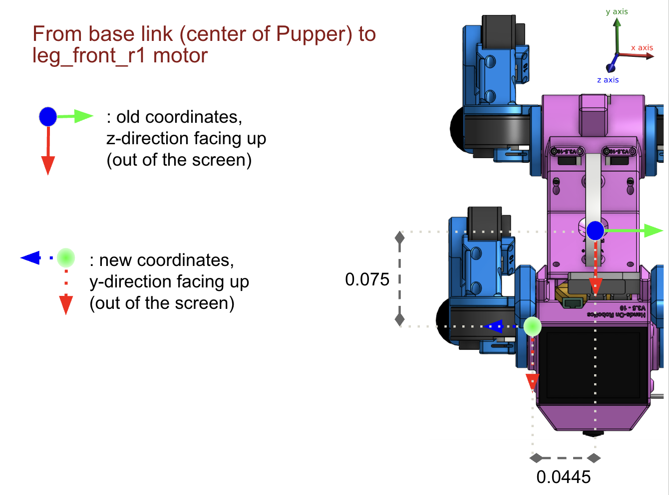
Transformation from base link to leg_front_r_1
DELIVERABLE: Explain the reasoning behind this implementation. What does the translation and each of the rotations do in T_0_1?
Implement the transformation matrix from leg_front_r_1 to leg_front_r_2 in
T_1_2. Follow the same thought process as withT_0_1. Check out the figure below for visual reference.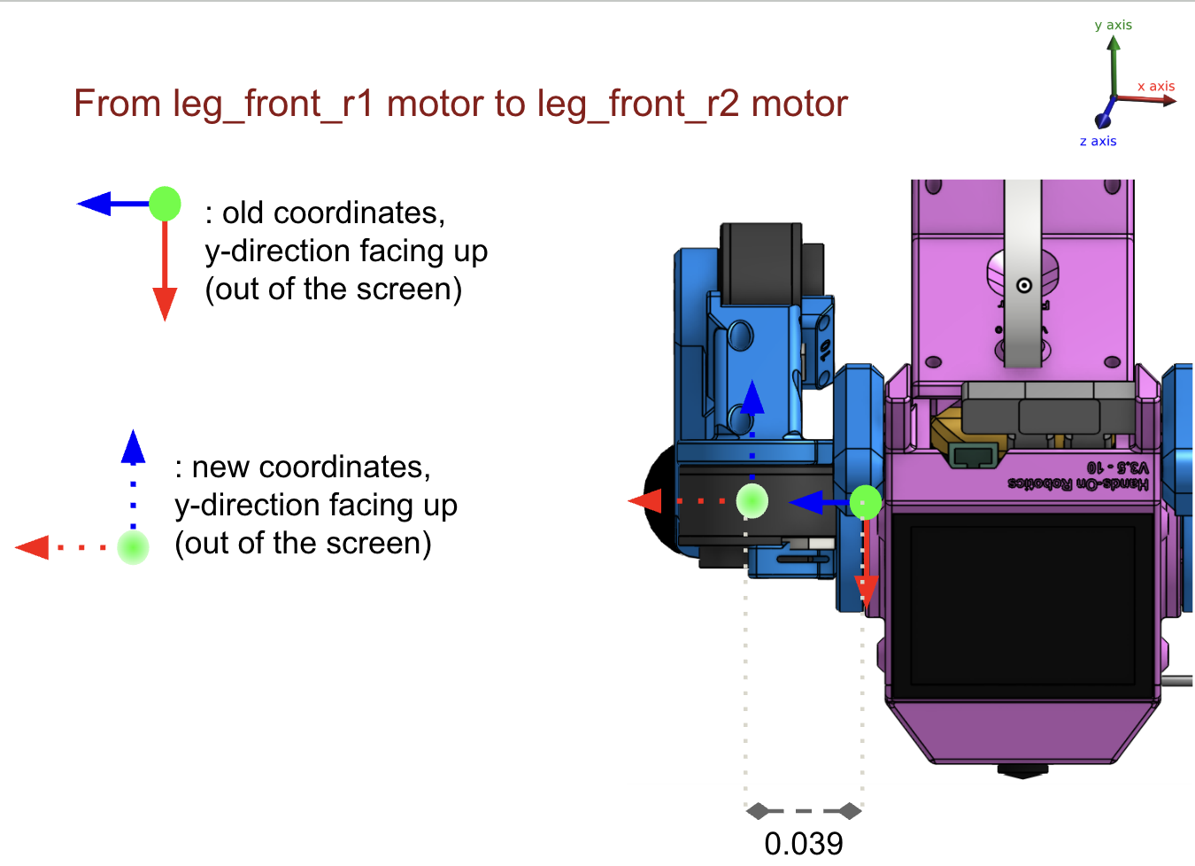
Transformation from leg_front_r_1 to leg_front_r_2
Implement the transformation matrix from leg_front_r_2 to leg_front_r_3 in
T_2_3. Check out the figure below for visual reference.
Transformation from leg_front_r_2 to leg_front_r_3
Implement the transformation matrix from leg_front_r_3 to the end effector in
T_3_ee. Check out the figure below for visual reference.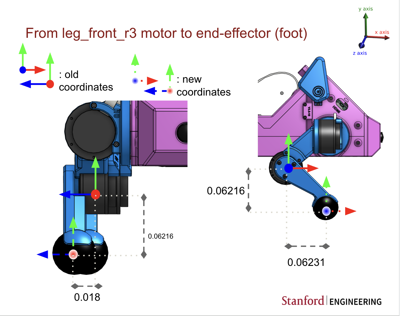
Transformation from leg_front_r_3 to the end effector
Compute the final transformation matrix following the described process from lecture in
T_0_ee. Remember that the end effector position is not in homogeneous coordinates. Calculateend_effector_positionfromT_0_ee.Note
The translation values may need to be adjusted based on the actual dimensions of your robot. Make sure to verify these values with your robot’s specifications.
DELIVERABLE:
Write out the full equation you used to calculate the forward kinematics (in math). Please use LaTeX and take a screenshot, or use the equation functionality in Google Docs. What is the benefit of using homogeneous transformations?
Why is there a 1 in the bottom-right corner of a homogeneous transformation matrix?
Part 5: Testing Your Implementation
Save your changes to
lab_2.py.Run the ROS2 nodes:
ros2 launch lab_2.launch.py
In another terminal, use the following command to run the main code:
python lab_2.pyMove the right front leg of your robot and observe the changes in the published positions.
To test your code in simulation to make sure that the code works as expected, you can use RVIZ. RVIZ will show the Pupper model as well as a marker that shows the output from the forward kinematics.
rviz2 -d lab_2.rviz
The above command will load the RVIZ config file. If you just run rviz, you can manually add the configuration. After running rviz, click the “Add” button, and then select a Robot Model type. Select the /robot_description topic. Next, add the marker by selecting “Add” again, and select a Marker type. Select the topic /marker.
Note
While we’ve tested this pipeline on a Pupper and it works as expected, rviz may fail on your robot due to heating in the Raspberry Pi. If this happens, reach out to a TA to check the implementation first, then turn off Pupper, wait a while to let it cool down, and try again.
DELIVERABLE: Take a video of the working implementation with you moving Pupper’s leg and the simulation mimicking the results and upload it to the Google Drive
Part 6: Analyzing the Results
Record the end-effector positions for the front right leg configurations.
Compare these positions with the expected positions based on the physical dimensions of your robot. (Why are the numbers printed in the terminal so small?)
If there are discrepancies, try to identify the source of the errors. It could be due to:
Incorrect transformation matrices
Inaccurate joint angle readings
Errors in the physical measurements of the robot
DELIVERABLE:
Measuring the correct physical parameters of the robot (leg lengths, motor angles, etc.) is essential to compute accurate kinematics. This process is called system identification. How would your estimate of the end effector (EEF) position change if your estimate of leg link 2 (r2) is off by 0.2 cm short from the actual distance to leg link 1 (r1)? What about 0.4 cm, or 0.8 cm? Write out the numbers you computed, and how you calculated them, for both 0 degrees rotation in each of the joints, and 45 degrees rotation in each of the joints. Qualitatively, how does error in estimated EEF position change with respect to error in leg length?
How does computational complexity of FK scale with respect to degree of freedom (number of motor angles)? Please use big O notation.
Additional Challenges (Optional)
If you finish early and want to explore further:
Extend your implementation to calculate forward kinematics for all four legs of the Pupper robot. Save your calculations for these other legs for lab 4, where we will need forward kinematics for all four legs.
We provide the base link to leg_back_r1 transformation in the diagram below. The rest of the transformations are identical to the right front leg:

Base to back right leg transformation diagram
During the testing of rviz, write a script that saves the sequence of your well-crafted motion, recorded as end effector positions into a file. You will have a chance to let Pupper replay this recorded motion in the next lab! You will need to use the
joint_statestopic to record the motor angles, and theleg_front_r_end_effector_positiontopic to record the end effector positions.
Friendly reminder: These are by no means any of the “optional labs” yet for this quarter. The first optional lab will be released next week, and it will be much more challenging/fun/frustrating/rewarding than these ;)
Remember, understanding forward kinematics is crucial for robot control and motion planning. Take your time to ensure you understand each step of the process.