Lab 2: Bad Robot Surgeon
Part One: Bad Robot Surgeon
Goal: Build two robot arms that mirror each other’s motion.
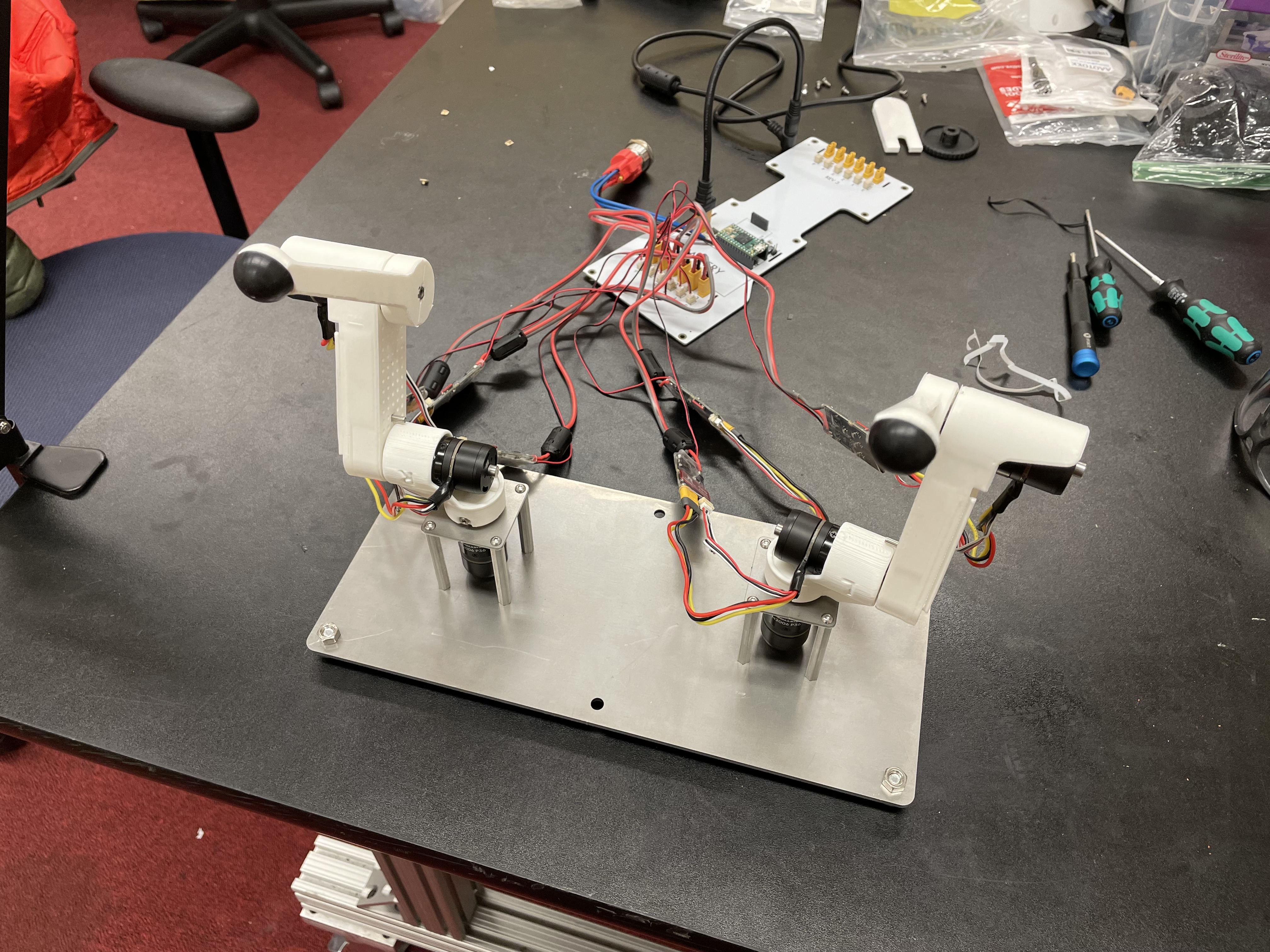
Assembled teleop robot arms
Step 0. Clone the starter code
In the directory of your choice, git clone the starter code for Bad Robot Surgeon
git clone https://github.com/cs123-stanford/lab_2_bad_robot_surgeon.git
cd lab_2_bad_robot_surgeon
git submodule init
git submodule update
Step 1. Connect 2 more motors
Connect power and encoder cables from motors to controllers.
Connect power and CAN cables from controllers to Pupper PCB. Make sure the CAN cables go into the same row (row near the Teensy).
Set the new motor controllers to have different IDs. Use 1, 2, and 3. Important: To set a motor controller to a certain ID, click (short press) press to put the motor controller into id-setting mode, then click N more times in quick succession, where N is the desired ID. Eg, for a desired ID of 3, press 3 more times after the first click. Unplug the CAN (small) cables from the PCB while setting ID’s to make it easier, otherwise they may conflict while you are changing them
Step 1.5. Control the 3 motors together
Modify your PD control code from lab 1 to control all 3 motors (controlled independently). Modify only the
back_stateMotorState array here.
[TODO: insert pic of compeleted setup]
Step 2. Insert square nuts into plastic parts
You may need to use force to get them in. The screw hole of the square nut must exactly align with the screw hole on each of the parts, as a long screw will attach through there.
Step 3. Connect and calibrate electronics
The motors should be calibrated in this way
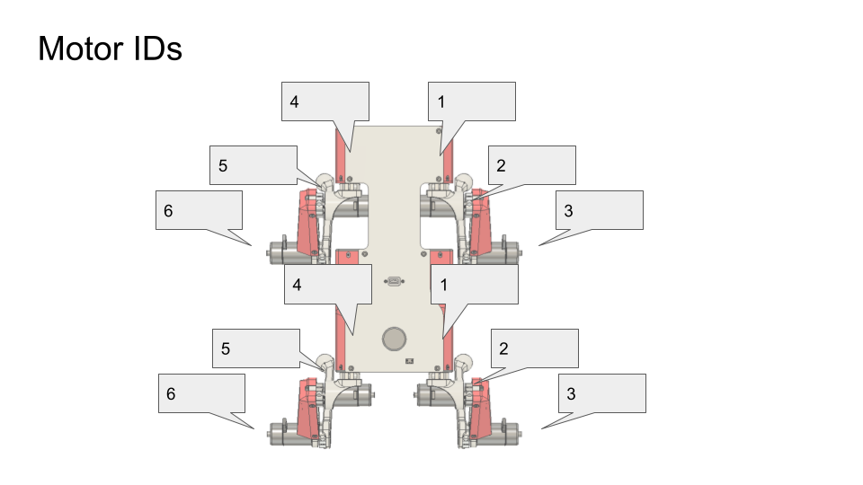
Motor IDs: use 1-3 for the front leg, and 1-3 for the back leg. Both should be right-hand-sided legs
IMPORTANT: Calibrate each motor before you assemble the arm, so that they get an accurate calibration with no load. Once you calibrate the motor, keep it with the motor controller you calibrated it on. The calibration is dependent on the motor controller, so that motor is now paired with the motor controller. If in doubt, recalibrate.
DELIVERABLE: Take a video of the motor controllers blinking with the correct IDs as decribed above. This is just to ensure that the motors are calibrated and connected before building the full leg, or else reassembly would be necessary.
Step 4. Assemble the three motors into a right robot arm!
IMPORTANT: Make sure you calibrated the motors before assembling the arm!
The robot arm we’re making is actually one of Pupper’s right legs so you’ll see the instructional videos reference it as such.
Assembly Pro Tips
Use the tip of the hex driver to align the shoulder bolt with the square nut. This will make assembly much easier.
Use force when inserting the shoulder bolts. Sometimes it is hard to get them through the hole in the motor shaft even if perfectly aligned.
Tighten the shoulder bolts as tight as possible without stripping. It is vital for the future stability of your Pupper!
Step 5. Run your code again on the new robot arm
Note that the “zero” position of these motors is whatever position it was at when the Teensy and motor were first both powered on.
Upload and run your code for controlling the 3 motors simultaneously.
Example where the arm PID positions targets are set so that it stands up vertically.
Step 6. Connect three more motors to use as control dials
Connect three additional motors to the same CAN bus (ie same row of connectors).
Calibrate and connect three additional motors to the Pupper PCB.
Set their IDs to not overlap with your existing motors. We use 4, 5, and 6.
Set the target positions of the base motor, shoulder motor, and elbow motor to the angle readings of the first, second, and third new motors respectively. Use the
front_stateMotorState array for this.
[TODO: gif]
Step 7. Connect and calibrate electronics for second right robot arm
Make sure that both arms are right-hand-sided (3d printed parts are marked with R and L)
Step 8. Assemble the three new motors into a robot arm
We’re now making one of Pupper’s left-side legs to use as the second robot arm.
Step 9. Use the arms as leader and follower.
Use the same code as in Step 6 where one set of motors controllers the other.
Start the robot arms from the same position.
Tune Kp and Kd gains and maximum current as you like.
DELIVERABLE: Submit a video of your leader/follower setup where you move all 3 joints of the leader, showing the follower copying the movements. Report on the differences you noticed between tuning the multi-joint setup versus the single dial setup in your lab document
[TODO: pic]
Step 10. Make the robot arms bidirectional!
Program position control for the leader arm actuators (formerly control dial actuators)
Set the position targets of the leader arm to the positions of the follower arm.
Assuming the leader arm has controller IDs 1, 2 and 3, and the follower arm has controller IDs 4, 5 and 6, you can send current (ie torque) commands to the robot arms with the code
bus_back.CommandTorques(back_state[0].cmd, back_state[1].cmd, back_state[2].cmd, 0 , C610Subbus::kIDZeroToThree);
bus_front.CommandTorques(front_state[0].cmd, front_state[1].cmd, front_state[2].cmd, 0 , C610Subbus::kIDZeroToThree);
DELIVERABLE: Submit a video like the leader/follower video where you move both arms manually, first moving the front, and then the back, to show bidirectionality
Congrats. Play with your robot! Make modifications!
[TODO: gif]
Part Two: Forward Kinematics
Goal: Program forward kinematics to determine the robot arm’s cartesian coordinates and create a haptic-feedback safety box.
Step 0. Get the starter code
In the directory of your choice, git clone the starter code for Forward Kinematics.
git clone https://github.com/cs123-stanford/lab_2_fk.git
cd lab_2_fk
git submodule init
git submodule update
Step 1. Prepare hardware
For this part of the lab, you only need to use one arm. The other arm will come in handy for the full Pupper build.
Set the controller for the base actuactor of the robot arm to 1 (1 blink).
Set the controller for the shoulder actuactor of the robot arm to 2 (2 blinks).
Set the controller for the elbow actuactor of the robot arm to 3 (3 blinks).
Make sure all the motor controllers are plugged into the CAN 2 bus (the set of connectors near the Teensy).
Step 2. Implement and test a forward kinematics function
Determine if you have a right or left robot leg (there’s a L or R on the lower link).
Update line 15 of src/main.cpp based on the what side leg you have.
Complete the forward_kinematics function inside of src/kinematics.h using what you learned in lecture. You should return a BLA::Matrix<3> of the cartesian coordinates of the end-effector.
Upload code.
Press s to start. The starter code will first test your kinematics code and then run the main loop.
Step 3. View cartesian coordinates of end effector
Start the robot from the zero position. See picture below
Print out the cartesian coordinates of the end effector using your forward kinematics function
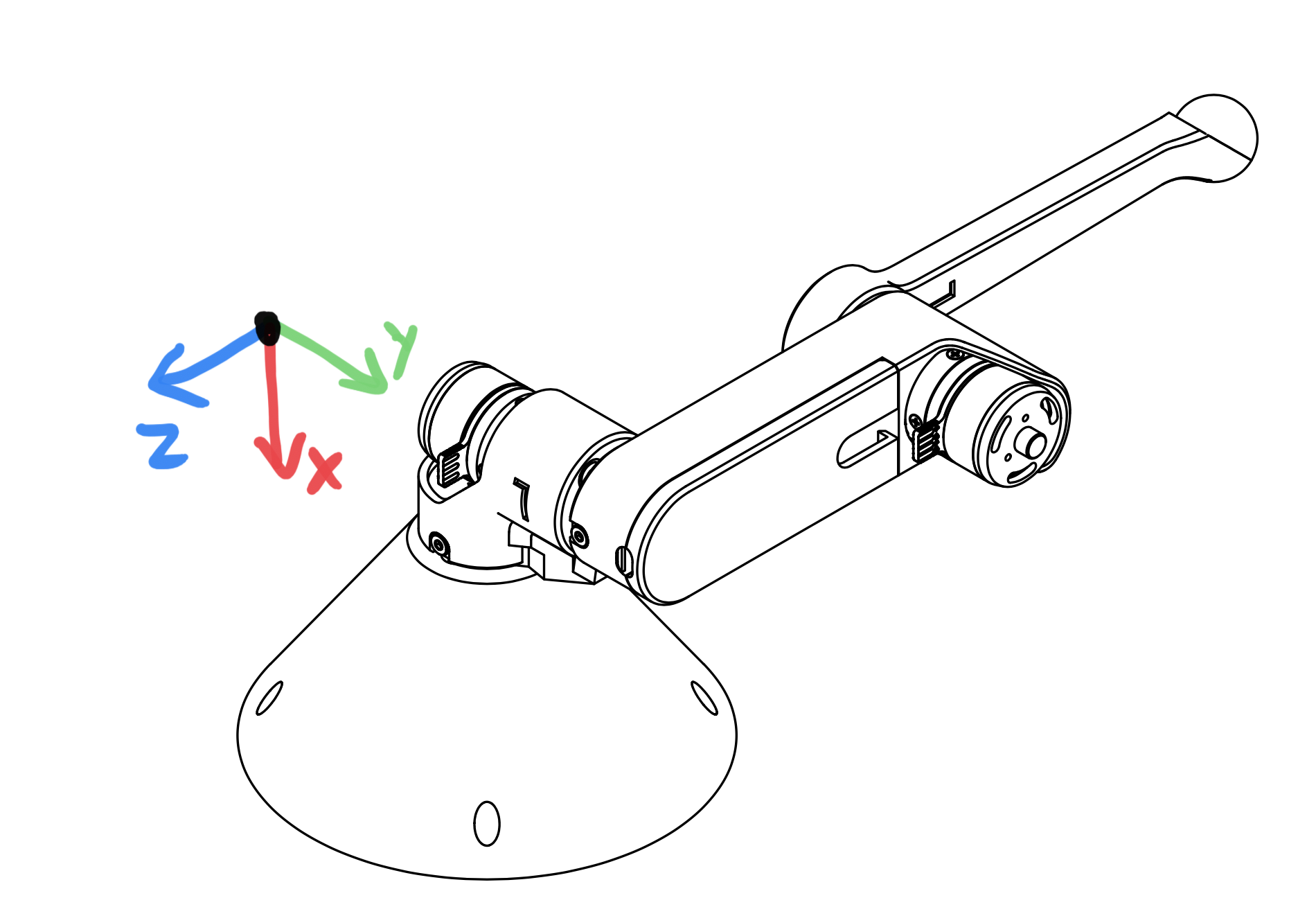
A left robot arm in the starting position for lab 2 and its coordinate system.
Step 4. Make a safety box
Pick a “safety” box – a virtual box in cartesian coordinates that the robot can operate safely in. For example, -0.1<x<0.1 and -.1<y>0.1 and 0<z<-0.2.
Print a warning whenever the robot leaves the safety box.
DELIVERABLE: Submit a video of you moving the robot arm outside of the safety bounds, and the serial monitor output printing an outside bounds message
Step 5. Do the safety dance
Make a function to vibrate the motors (high frequency, low amplitude alternating torque command)
If you program an alternating torque, a safe range for the amplitude is around 800 - 3000mA. Any lower is barely perceptible.
Run the function whenever the robot end effector leaves the safety box. A suggested implementation is to alternate the torque current command on each control loop iteration.
DELIVERABLE: Submit a video of you moving the robot arm outside of the safety bounds, and the arm’s haptic feedback response. Report what amplitude you chose for the haptic feedback
[gif of completed project]
References for Derivation of FK
Mini-lecture - Forward Kinematics
3D illustration of motor angles, directions of positive rotation, and relevant geometry.
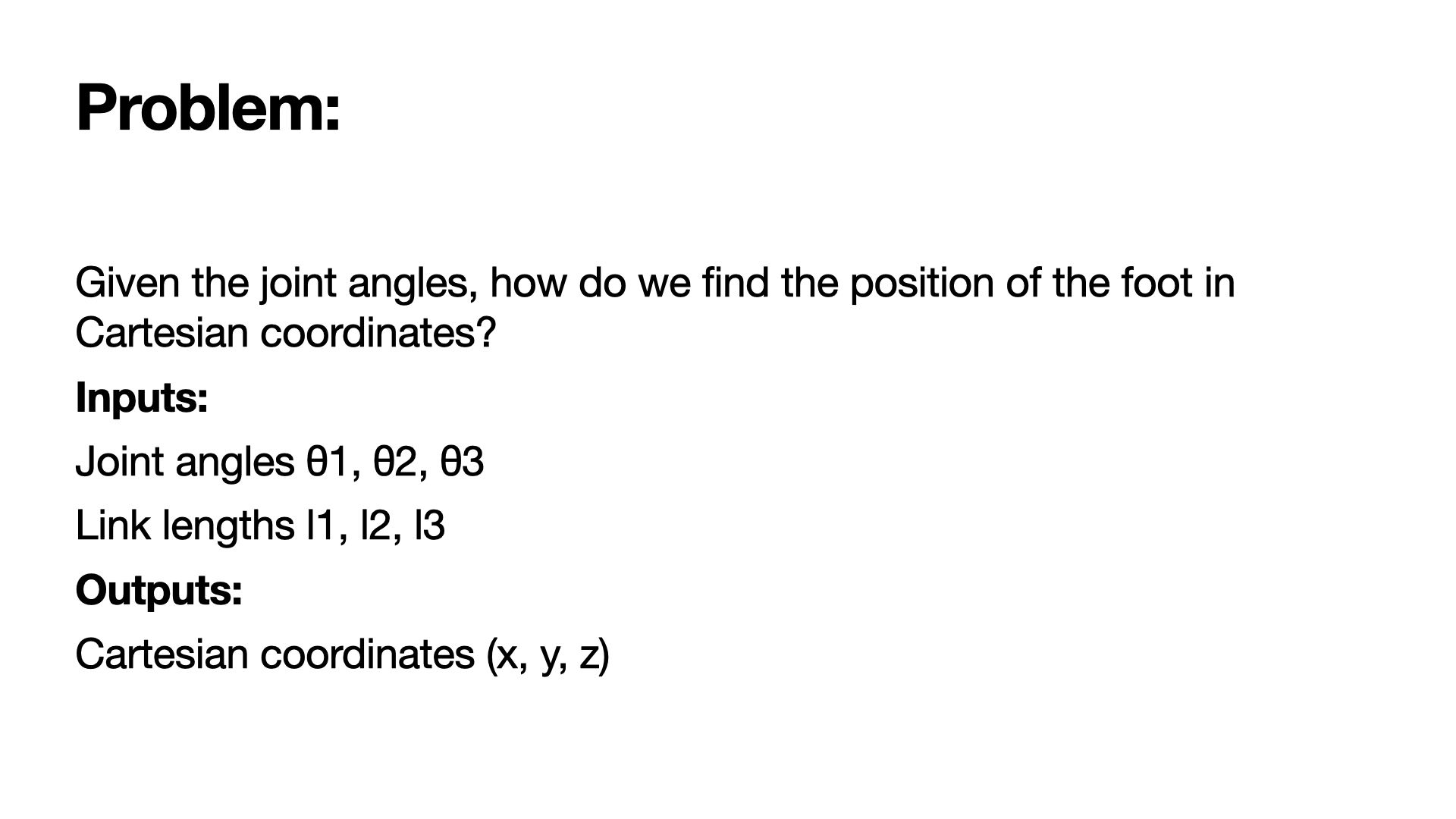
Problem statement.
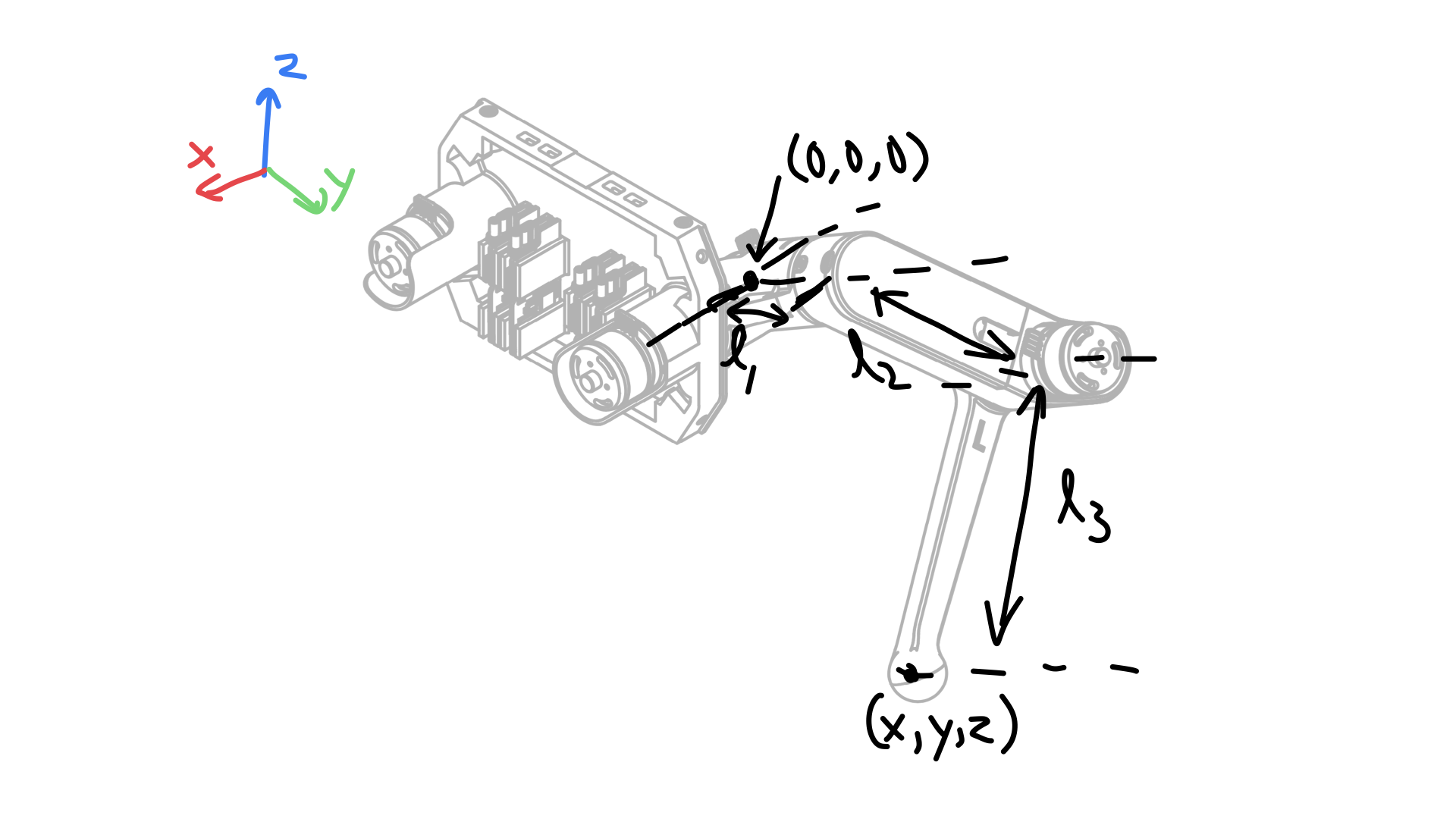
Coordinate frame, link lengths, and leg origin illustration.
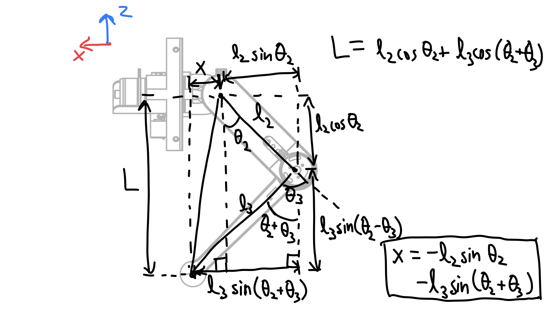
Derivation of x coordinate of foot and L.
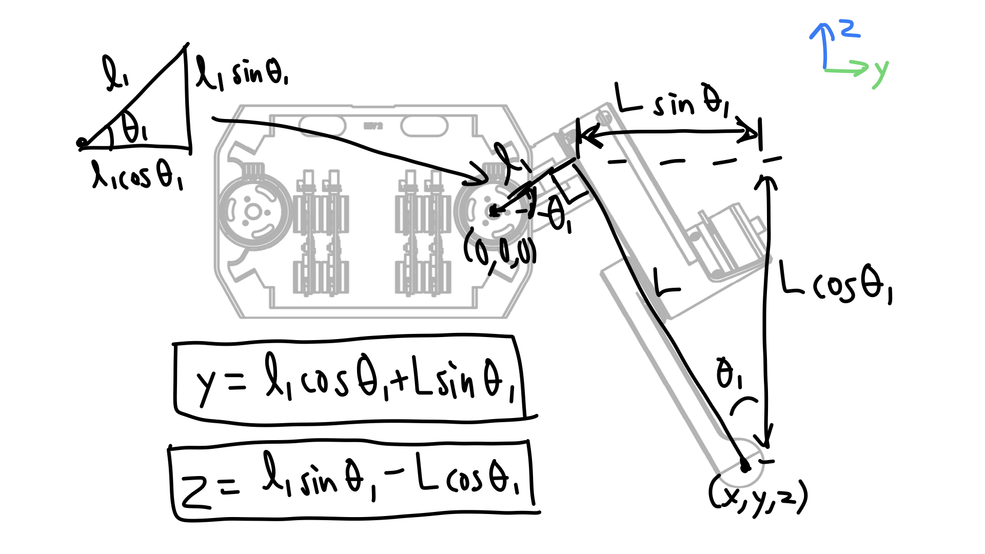
Derivation of y and z coordinate of foot.